Generating electric currents
We saw that a change in the magnetic flux passing through a transformer's secondary coil causes current to flow in that coil. Since the magnetic flux through the secondary coil changes whenever the current through the primary coil changes, an alternating current in
the transformer's primary coil induces an alternating current in its secondary coil.
But there's another way to change the magnetic flux passing through a coil of wire: move the magnetic flux. That's how a generator works. Whenever a magnet moves past a coil of wire or a coil of wire moves past a magnet, the flux through the coil changes and current flows in the coil and its circuit.
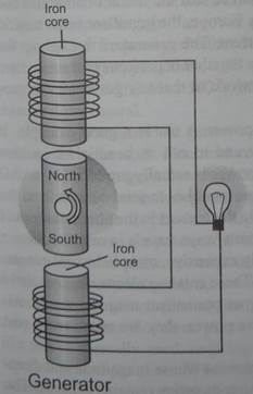 Most generators use rotary motion to produce electricity. The generator has a permanent magnet that spins between two fixed coil of wire. As the magnet spins, its magnetic flux lines sweep through the two coils and drive a current through them. This current experiences a volt age rise as it passes through the coils and a volt age drop as it passes through the light bulb, so it transfers power from the generator to the bulb.
The iron core inside each coil extends the magnet's flux lines so that they are sure to sweep through the coil each time a pole of the magnet passes by. These cores are temporarily magnetized by the nearby magnet and effectively increase its length. Without the iron cores, most of the rotating magnet's flux lines would bend around before passing through the entire coil and the generator would be less effective at producing electricity.
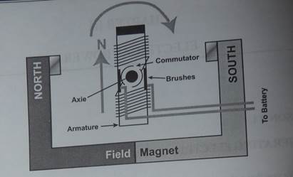
In the above diagram, you can see two magnets in the motor: The armature (or rotor) is an electromagnet, while the field magnet is a permanent magnet (the field magnet could be an electromagnet as well, but in most small motors it isn't in order to savepower). The principle design of the motor is identical to the generator. A generator produces an alternating current in the circuit it powers. This current flows in one direction as the magnet's north pole approaches a coil and in the opposite direction as the south pole approaches it. To generate the 60 Hz alternating current used in the United States, the generator must turn 60 times each second so that the current completes one full cycle of reversals every l/60th of a second. In Europe, the generator must turn 50 times each second to supply 50 Hz alternating current. The generators throughout the continent-wide power distribution networks all turn together in perfect synchronization. That way, power can be redirected within each network so that any generator can provide the power consumed by any user.
Some devices require direct current electric power. A car is a good example. It generates DC electric power to charge its battery and to run its headlights, ignition system, and other electric components. While this power is actually produced by an AC generator or alternator, the car uses special electronic switches to send current from alternator one way through its electric system. While the current in the alternator's reverses, the current through the car's electric system always travels in one direction.
Because large permanent magnets are extremely expensive, most industrial generators actually use iron-core electromagnets instead. These rotating electromagnets drive currents through generator coils just as effectively as permanent magnets would. Al- though these electromagnets consume some electric power, they are much more соя effective than real permanent magnets.
An alternating current (AC)is an electrical current whose magnitude and direction vary cyclically, as opposed to direct current, whose direction remains constant. The usual waveform of an AC power circuit is a sine wave, as this result in the most efficient
transmission of energy. However in certain applications different waveforms are used, such as triangular or square waves.
Used generically, AC refers to the form in which electricity is delivered to businesses and residences. However, audio and radio signals carried on electrical wire are also examples of alternating current. In these applications, an important goal is often the recovery of information encoded (or modulated) onto the AC signal.
Electricity distribution
AC voltage can be stepped up or down by a transformer to a different voltage. High-voltage, direct current electric power transmission systems contrast with the mod common alternating-current systems as a means for the bulk transmission of еelectrical power. However, these tend to be more expensive and less efficient than transformers. Use of a higher voltage leads to more efficient transmission of power. The power losses in a conductor are a product of the square of the current and the resistance of the conductor, described by the formula P = I2R. This means that when transmitting a fixed power on a given wire, if the current is doubled, the power loss will be four times greater. Since the power transmitted is equal to the product of the current, the voltages also and the cosine of the phase difference cp (P = IVcosφ), the same amount of power can be transmitted with a lower current by increasing the voltage. Therefore it is advantageous when transmitting large amounts of power to distribute the power with extremely high voltages (sometimes as high as hundreds of kilovolts). However, high voltages also have disadvantages, the main ones being the increased danger to anyone who comes into contact with them, the extra insulation required, and generally increased in their safe handling. In the power plant the voltage is generated on three phase low voltage, with a frequency of either 50 or 60 hertz, and stepped up to a high voltage for distribution and stepped down, with a neutral, to a relatively low level for the com generally around 200 V to 500 V between phases and 100 V to 250 V between each phase and the neutral.
Three-phase electrical generation is very common and is a more efficient use of commercial generators. Electrical energy is generated by rotating a coil inside magnetic field, in large generators with a high capital cost. However, it is relatively simple and cost effective to include three separate coils in the generator stator (instead of one). These sets of coils are physically separated and at an angle of 120° to each other. Three current waveforms are produced that are 120° out of phase with each other, but of equal magnitude. Three-phase systems are designed so that they are balanced at the load; if a load is correctly balanced no current will flow in the neutral point. Also, even in the worst-case unbalanced (linear) load, the neutral current will not exceed the highest of the phase currents. For three-phase at low (normal mains) voltages a four-wire system like this is normally used, reducing the cable requirements by one third over using a separate neutral per phase. When stepping down three-phase, a transformer with a Delta primary and a Star secondary is often used so there is no need for a neutral on the supply
side. For smaller customers (just how small varies by country and age of install) only a single phase and the neutral or two phases and the neutral are taken to the property. For larger installs all three phases and the neutral are taken to the main board. From a three-phase main board both single and three-phase circuits may lead off (and in some cases also circuits with two phases (not to be confused with two-phase) and a neutral are led off). Three-wire single phase systems, with a single centre-tapped transformer giving two live conductors, is a common distribution scheme for residential and small commercial buildings in North America. A similar method is used for a different reason on construction sites in the UK. Small power tools and lighting are supposed to be supplied by a local center-tapped transformer with a voltage of 55 V between each power conductor and the earth. This significantly reduces the risk of electric shock in the event that one of the live conductors becomes exposed through an equipment fault whilst still allowing a reasonable voltage for running the tools.
A third wire is often connected between non-current carrying metal enclosures and earth ground. This conductor provides protection from electrical shock due to accidental contact of circuit conductors with the case of portable appliances and tools.
AC power supply frequencies
The frequency of the electrical system varies by country; most electric power is generated at either 50 or 60 Hz. Some countries have a mixture of 50 Hz| and 60 Hz supplies.
A low frequency eases the design of low speed electric motors, particularly for hoisting, crashing and rolling applications, and commutator-type traction motors for applications such as railways, but also causes a noticeable flicker in incandescent lighting and objectionable flicker of fluorescent lamps. 16.67 Hz power (1/3 of the mains frequency) is still used in some European rail systems, such as in Sweden and Switzerland.
Textile industry, marine, computer mainframe, aircraft, and spacecraft applications sometimes use 400 Hz, for benefits of reduced weight of apparatus or higher speeds.
AC-powered appliances can give off a characteristic hum at the multiples of the frequencies of AC power that they use. Most countries have chosen their television standard to approximate their mains supply frequency. This helps prevent power line hum and magnetic interference from causing visible beat frequencies in the displayed picture. Unless specified by the manufacturer to operate on either 50 or 60 Hz, appliances may not operate efficiently or even safely if used on other than the intended supply frequency.
The European Union (including the UK) has now officially harmonized on a supply of230 V 50 Hz. However they made the tolerance bands very wide at ±10%. Some countries actually specify stricter standards than this for example the UK specifies 230 V +10% -6%. Most supplies to the old standards therefore conform to the new one and do not need to be changed.
To be continued.
WORDLIST:
Alternating current (AC) переменный ток
primary coil первичная обмотка
secondary coil вторичная обмотка
magnetic flux магнитный поток,
магнитные силовые линии
step up transformer повышающий трансформатор
step down transformer понижающий трансформатор
permanent magnet постоянный магнит
iron core стальной сердечник
commutator коллектор, коммутатор
brush, brush gear щетка, щеточное устройство
armature якорь
rotor ротор
stator статор
sine wave синусоидальное колебание(волна)
conductor проводник
resistance сопротивление
current ток, сила тока
main board центральный (сетевой) щит
live conductor провод под напряжением, фазньй
center-tapped transformer трансформатор с
выведенной cредней точкой
power (circuit) conductor силовой провод
commutator type коммутационный тяговый двигать
traction motor
incandescent lighting освещение лампами накаливания
computer mainframe базовая компьютерная сеть
to induce индуктировать; наводить
winding обмотка
to rectify выпрямлять
field magnet возбуждающий магнит; индуктор
series последовательный
shunt шунтовой, параллельный
compound смешанный
EXERCISES:
I. Answer and translate the following questions:
a) What is an electrical generator?
b) What is the type of power supply at your home?
c) Give us main parts of a generator's design.
d) Does an electrical motor have the same design as a generator?
e) The electrical current is dangerous, isn't it? How can you protect yourself from it?
f) Is it possible to combine a motor and a generator in one unit?
II. Translate the following sentences:
a) The generator has a permanent magnet that spins between two fixed coils of wire.
b) Without the iron cores, most of the rotating magnet's flux lines would bend around before passing through the entire coil and the generator would be less effective at producing electricity.
c) To generate the 60 Hz alternating current the generator must turn 60 times each second so that the current completes one full cycle.
d) The generators throughout the continent-wide power distribution networks all turn together in perfect synchronization.
e) AC voltage can be stepped up or down by a transformer to a different voltage.
f) Three current waveforms are produced that are 120° out of phase with each other, but of equal magnitude.
g) Three-wire single phase systems, with a single centre-tapped transformed two live conductors, is a common distribution scheme for residential and small commercial buildings.
h) AC-powered appliances can give off a characteristic hum at the multiples of the frequencies of AC power that they use.
III. Translate the following text into Russian:
Alternator
The alternating current generator, or alternator, is the electrical system’s chief source of power while the engine is running . Its shaft is driven by the same belt that spins he fan. It converts mechanical energy into alternating current electricity, which is then channeled through diodes that alter it to direct current for the electrical system and I for recharging the battery.
Is your Alternator big enough for all your electrical equipment? If you have a large stereo system you'll know that it is not when the bass thumps ... you may see yourheadlights and dash lights dim. Each 100 watt lamp is going to draw about 9 amps so six of them is going to suck up about 55 Amps. The other accessories on your car cooling fan, heater fan, ignition, fuel pump, running lights, etc. - are going to draw roughly another 30-40 Amps - your total power requirement will reach about 90-100 Amps. Add more lights, large stereo system, a winch, and you may find yourself with an overworked alternator.
It's impossible to compensate for a small alternator by throwing in a bigger battery as the battery will just be drained and the voltage will suffer, affecting your light output and overall performance. Your best solution is to go to a modern, high output alternator f at least 100 Amps or more. If you are ready wort d about weight, you’re better off with a smaller battery. All it really has tjo do is start the engine if the alternator is larg enough to carry the rest of the car is running.
IV. Translate the following information into English:
Машины постоянного тока.
К машинам постоянного тока относятся генераторы и электрические двигатели. Машина постоянного тока состоит из двух основных частей: а) неподвижной части (статор), предназначенной для создания магнитного потока, б) вращаюяющейся части (ротора), которая называется якорем и в которой происходит процесс преобразования механической энергии в электрическую (электрический генератор); или обратно - электрической энергии в механическую (электродвигатель)» Небольшой зазор отделяет статор от ротора.
Статор машины постоянного тока состоит из: а) основных полюсов – для созданиямагнитного потока; б) добавочных полюсов (interpoles), установленных между основными для обеспечения безыскровой работы щеток коллектора и станины
Якорь - это цилиндрическое тело, вращающееся в пространстве между полюсами, и состоит из: а) зубчатого цилиндрического якоря; б) обмотки, уложенной на нём; в) коллектора; г) щеточного устройства.
LESSON #2
DIRECT CURRENT
Direct current (DC or "continuous current") is the constant flow of electric charge
from high to low potential. This is typically in a conductor such as a wire, but can also be through semiconductors, insulators, or even through a vacuum as in electron or ion beams. In direct current, the electric charges flow in the same direction, distinguishing it from alternating current (AC).
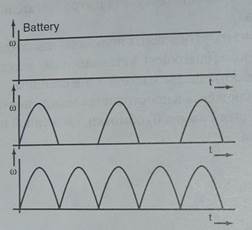
Types of direct current
The first commercial electric power transmission (developed in the late nineteenth century) used direct current. Because alternating current is more convenient matt current for electric power distribution and transmission, today nearly all electric rower transmission uses alternating current.
Various definitions
Within Electrical Engineering, the term DC is a synonym for constant. For example, the voltage across a DC voltage source is constant as is the current through J current source. The DC solution of an electric circuit is the solution where all voltages and currents are constant. It can be shown that any voltage or current waveform can decomposed into a sum of a DC component and a time-varying component. The DC component is defined to be the average value of the voltage or current over all time. THE average value of the time-varying component is zero.
Although DC stands for "Direct Current,DC sometimes refers to "constant polarity”
With this definition, DC voltages can vary in time, such as the raw output of a rectifier. Some forms of DC (such as that produced by a voltage regulator) have almost no variations in voltage, but may still have variations in output power and current.
Applications
Direct current installations usually have different types of sockets, switches, and fixtures, mostly due to the low voltages used, from those suitable for alternating current. It is usually important with a direct current appliance to not reverse polarity unless the device has a diode bridge to correct for this. (Most battery-powered devices don't.)
High voltage direct current is used for long-distance point-to-point power transmission and for submarine cables, with voltages from a few kilovolts to approximately megavolt.
DC is commonly found in many low-voltage applications, especially where these are powered by batteries, which can produce only DC, or solar power sys solar cells can produce only DC. Most automotive applications use DC, although the generator is an AC device which uses a rectifier to produce DC. Most electronic circuits require a DC power supply.
Power supplies
Audio Amplifier
Power-line operated power supplies are based on transformers, diodes, 1 and capacitors. Transformers enable these supplies to exchange voltage for current to obtain the large currents and low voltages needed by audio amplifiers and other house-hold electronic devices. Diodes prevent currents from flowing backward through these supplies so that, like batteries, they always pump currents from their negative terminals to their positive ones. Transistors help to control the voltage of the current delivered by a power supply-they cause the output current to experience an adjustable and carefully controlled voltage drop so that the current leaves the supply at a regulated voltage. And capacitors in the supply store separated electric charge and energy for delivery during the times when the supply isn't receiving any power from the alternating current source.
A basic power supply, without any transistor regulation, connects the primary of its transformer to the electric outlet and the secondary of that transformer to a set of diodes. These diodes act as electronic switches, directing current always in one direction through the circuit that the power supply operates. To stop the current from fluctuating so much, capacitors are often attached to the two output wires of the power supply. These capacitors store separated charge during times when the AC power line is delivering more than enough current and release some of that charge with the power line isn't delivering enough.
In more sophisticated modern power supplies, often called "switching power supplies," current from the electric outlet is sent through diodes and into capacitors, where it is stored as separated charge. Several transistors then act as electronic
switches to produce a high-frequency alternating current from this stored charge. With a frequency of tens of thousands of cycle* per second, this current passes through the primary of a small transformer. Only a small transformer is needed because the short duration of a cycle reduces the amount of energy that the transformer needs to store in its magnetic field during one cycle. Power passes to a current in the transformer's secondary coil. This secondary coil current is rectified (made DC) by passing it through more diodes. The DC current is filtered with more capacitors and a final transistor stage controls the delivery voltage. But the main delivery voltage control comes from turning on or off the high-frequency AC that is synthesized and delivered to the transformer's primary coil. By starting or stopping this AC current, the power supply can control the flow of power through the transformer and ciently limit the voltage of its overall output.
WORDLIST:
Semiconductor - полупроводник
insulator - изолятор
ion beams - ионные лучи
electric power transmission - передача электроэнергии
electrical engineering -электротехника
installations - (зд.) аппаратура, оборудование
fixtures- - контактирующие приспособлен
diode bridge - диодный мост
point-to-point -двухточечная (сквозная) пepeдача
power transmission электроэнергии
submarine cable - подводный кабель
audio amplifier - звуковой усилитель
capacitor - конденсатор
electronic switch - электронный выключатель
(коммутатор)
EXERSICES:
I. Decipher and translate the following abbreviations:
I AC generator, DC, elec, eng, neg, ft, 12in, 1.5yd, pos, 3,000 r.p.m, 5kW DC motor, e.m.f., h.v. power supply, 220v 50 Hz mains
II. Answer the following question:
a)What type of the current is there in your cell phone?
b) Does a car accumulator is a source of AC, isn't?
c) What types of DC do you know?
d) What type of the power supply may be used for portable calculator?
e) What transformers are designed for?
f) Can you distinguish any difference between terms converter and inverter?
g) Is it possible to use DC installations in AC power supply lines?
h) Do you know electrical motor which can run on either DC or AC electric power?
III. Translate the following text into Russian:
Universal Motors
If you replace the permanent magnets of a DC motor with electromagnets and connect these electromagnets in the same circuit as the commutator and rotor, you will have a universal motor. This motor will spin properly when powered by either direct or alternating current.
When you connect DC power to a universal motor, the stationary electromagnets j will behave as if they were permanent magnets and the universal motor will operate just like a DC motor. The only difference is that the universal motor will not reverse directions when you reverse the current passing through it. It will continue turning in the same direction because reversing the current through the rotor also reverses the current through the electromagnets. Since the universal motor contains no permanent magnets, every pole in the entire motor changes from north to south or from south to north. Because all the poles change, the motor's behavior does not. It keeps turning in the same direction. If you really want to reverse the motor's rotational direction, you must rewire the stationary electromagnets to reverse their poles.
Since the universal motor always turns in the same direction, regardless of which way current flows through it, it works just fine with AC electric power. Universal motors are commonly used in kitchen mixers, blenders, and vacuum cleaners. While these motors are cheap and reliable, their graphite brushes eventually wear out and must be replaced. To repair a motor with a worn brush, you simply remove what's left of the old brush and replace it with a new one from the nearest hardware store.
IV. Translate the following material into English:
Трансформатором называется статический электромагнитный аппарат, пред- назначенный для преобразования переменного тока одного типа (первичного) в переменный ток с другими характеристиками, такими как другое напряжение и сила тока. Трансформатор состоит из: 1) сердечника, выполненного из трансформаторной стали, и 2) двух или нескольких обмоток, связанных между собой электромагнитным полем. Трансформатор с двумя обмотками называется двухобмоточный; а с несколькими обмотками - многообмоточными. По роду тока различают трансформаторы однофазные, трехфазные и многофазные.
Обмотка трансформатора, к которой подводится переменный ток, называется первичной обмоткой, а обмотка на выходе - вторичной. Если напряжение на выходе трансформатора выше первичного, то трансформатор называется повышающим, а если ниже — понижающим.
ADDITIONAL MATERIAL:
Arc weldingrefers to a group of welding processes that use a welding power supply to create an electric arc between an electrode and the base material to melt the metals at the welding point. They can use either direct (DC) or alternating (AC) current, and consumable or non-consumable electrodes. The welding region is sometimes protected by some type of inert or semi-inert gas, known as a shielding gas, and/or filler material.

A constant current welding power supply capable of AC and DC
To supply the electrical energy necessary for arc welding processes, a number of different power supplies can be used. The most common classification is constant current power supplies and constant voltage power supplies. In arc welding, the voltage is directly related to the length of the arc, and the current is related to the amount of heat input. Constant current power supplies are most often used for manual welding processes such as gas tungsten arc welding and shielded metal arc welding, because they maintain a relatively constant current even as the voltage varies. This is important because in manual welding, it can be difficult to hold the electrode perfectly steady, and as a result, the arc length and thus voltage tend to fluctuate. Constant voltage power supplies hold the voltage constant and vary the current, and as a result, are most often used for automated welding processes such as gas metal arc welding, flux cored arc welding, and submerged arc welding. In these processes, arc length is kept constant, since any Electrical Power fluctuation in the distance between the wire and the base material is quickly rectified by a large change in current. For example, if the wire and the base material get too close, the current will rapidly increase, which in turn causes the heat to increase and the tip of the wire to melt, returning it to its original separation distance.
The direction of current used in arc welding also plays an important role in welding. Consumable electrode processes such as shielded metal arc welding and gas metal arc welding generally use direct current, but the electrode can be charged either positively or negatively. In welding, the positively charged anode will have a greater heat concentration and, as a result, changing the polarity of the electrode has an impact on weld properties. If the electrode is positively charged, it will melt more quickly, increasing weld penetration and welding speed. Alternatively, a negatively charged electrode results in more shallow welds. Non-consumable electrode processes, such as gas tungsten arc welding, can use either type of direct current, as well as alternating current. With direct current however, because the electrode only creates the arc and does not provide filler material, a positively charged electrode causes shallow welds, while a negatively charged electrode makes deeper welds. Alternating current rapidly moves between these two, resulting in medium-penetration welds. One disadvantage of AC, the fact that the arc must be re-ignited after every zero crossing, has been addressed with the invention of special power units that produce а square wave pattern instead of the normal sine wave, eliminating low-voltage time after the zero crossing and minimizing the effects of the problem.
LESSON # 3
MEASURING INSTRUMENTS
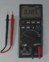 A multimeter set to measure voltage. Instruments for measuring potential differ-ences include the voltmeter, the potentiometer (measurement device), and the oscilloscope. The voltmeter works by measuring the current through a fixed resistor, which, according to Ohm's Law, is proportional to the potential difference across it. The potentiometer works by balancing the unknown voltage against a known voltage in a bridge circuit. The cathode-ray oscilloscope works by amplifying the potential difference and using it to deflect an electron beam from a straight path, so that the deflection of the beam is proportional to the potential difference.
A multimeter is an electronic measuring in-that combines several functions in one unit. The most basic instruments include an ammeter, voltmeter, and ohmmeter.
fultimeter can be a handheld device useful for basic fault finding and field serviceor a bench instrument which can measure to seven or eight and a half digits of accurancy. Such an instrument will commonly be found in a calibration lab and can be used to characterise resistance and voltage standards or adjust and verify the performance of multi-function calibrators.
Current, voltage, and resistance measurements are considered standard features for multimeter. AVO multimeters, a manufacturer of early multimeters, derived their name from amperes, volts, and ohms, the units used for the measurement of current, voltage, and rcsistance.
A multimeter may be implemented with an analog meter deflected by an electro-magnet, as a classic galvanometer; or with a digital display such as an LCD or Vacuum fluorescent display.
Analog multimeters are not hard to find in the used market, but are not very accurate because of errors introduced in zeroing and reading the analog meter face.
Analog meters may be implemented with vacuum tubes to precondition and amplify the input signal. Such meters are known as vacuum tube volt meters (VTVM) or vacuum tube multimeters (VTMM).
Modern multimeters are exclusively digital, and identified by the term DMM digital multimeter. In such an instrument, the signal under test is converted to a digital voltage and an amplifier with an electronically controlled gain preconditions the signal Since the digital display directly indicates a quantity as a number, there is no risk of parallax causing an error when viewing a reading.
Similarly, better circuitry and electronics have improved meter accuracy. Older analog meters might have basic accuracies of five to ten percent. Modern portable DMMs may have accuracies as good as ±0.025%, and bench-top instruments have accuracies
in the single-digit parts per million figures.
Digital meters often feature circuitry or software to accurately measure AC voltages at any frequency. These meters integrate the input signal using the root mean square method, and will correctly read the true voltage of an input signal even if it isn't a perfect sine wave.
Modem meters may be interfaced with a personal computer by IrDA links, RS-232 connections, or an instrument bus such as IEEE-488. The interface allows the computer to record measurements as they are made or for the instrument to upload a series of results to the computer.
As modern appliances and systems become more complicated, the multimeter is| becoming less common in the technician's toolkit. More complicated and specialized equipment replaces it. Where a service man might have used an ohmmeter to measure resistance while testing an antenna, a modern technician may use a hand-held analyzer to test several parameters in order to determine the integrity of a network cable
Read this useful information:
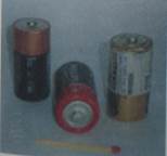 Common voltages
1.5 volt C-cell batteries
Nominal voltages of familiar sources:
Nerve cell action potential: 40 millivolts
Single-cell, rechargeable alkaline battery: 1.2 volts
Single-cell, non-rechargeable battery (e.g. AAA, AA, С and D cells): 1.5 volts
Lithium polymer rechargeable battery: 3.7 volts Automobile electrical system: 12 volts
Household mains electricity: 120 volts North America, 230 volts Europe and 220voltt, 50 Hz Russia.
Rapid transit third rail: 600 to 700 volts
Trams and trolleybus power supply in Russia: 600 volts
High voltage electric power transmission lines: 110 kilobits and up (1150 kV is the record as or 2005)
Lightning: 100 mega volts
WORDLIST:
Measuring instrument - электроизмерительные приборы
Multimeter - универсальный измерительный
Прибор,многофункциональный измерительный прибор; мультиметр
bridge circuit - мостик
cathode ray oscilloscope - элетронно-лучевой осциллограф
bench instrument - стендовый измерительный прибор
calibration - калибровка, проверка, тарирование
vacuum fluorescent display - вакуум-люминесценный дисплей (индикатор)
vacuum tube voltmeter - электровакуумный вольтметр
controlled gain - управляемое, регулируемое усилие
parallax - смещение
single-digit - одноразрядный
circuitry - компоновка схемы
root mean square method - метод среднеквадратных значений
sine wave -гармоничная волна; синусоидальное колебание
IrDA (infrared data association) - инфракрасный стандарт
instrument bus - шина для подключения приборов
interface - устройство сопряжения
analyzer - прибор для проверки; анализатор
rapid transit third rail - напряжение скоростного поезда (третий контактный рельс)
EXERCISES:
I.Translate thefollowing sentences:
a) The digital display directly indicates a quantity as a number, there is no risk of parallax causing an error when viewing a reading.
b) A multimeter can be a handheld device useful for basic fault finding and field service work or a bench instrument which can measure to seven or eight and a half digits of accuracy.
c) Вольтметр - это прибор для измерения разницы потенциалов между двумя
точками в электрической цепи.
d) As the resistance of the voltmeter is very high, the current passing through it is
very small.
e) The construction of a voltmeter and a ammeter may be the same. Each meter has a pointer which is deflected according to the current passing and the scale of ammeter is marked in amperes.
f) С помощью универсального измерительного прибора можно измерять
напряжение, ток и сопротивление в электрической цепи.
g) The final reading of the meter depends upon the strength of the current in the
power supply line.
II. Translate the following information in to Russian:
Electricity meters.
Fig. 2 shows a motor-type ampere-hour meter. It is in effect a small directs motor. The armature, or rotor, is an aluminum disc mounted in the field of а permanent
magnet. The disc contains three coils which are supplied with current from a commutator consisting of three sectors. The current to the rotor coils is proportional to the total current passing through the consumer installation, from which it is branched off. Since the field strength of the permanent magnet is J
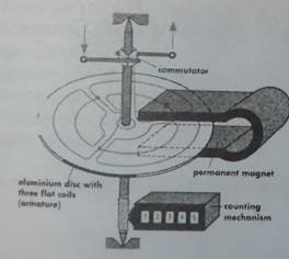
Fig.2 Motor type meter
constant, the speed of rotation of the rotor is proportional to the current strength. The counting mechanism connected to the rotor shaft counts the revolutions, which correspond to the product I.t. If, instead of the permanent magnet, an electromagnet is used to produce the magnetic field, and if the consumer voltage V is applied to this coil, thenthe speed of rotation of the rotor is proportional both to V and to I, and therefore the product V. I. In that case the counting mechanism directly records the energy V.l.t. The ampere-hour meter has thus become a true watt-hour meter.
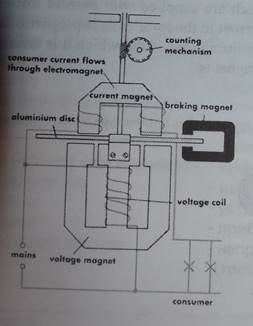
The kind of meter nowadays generally used for alternating current is the induction meter (Fig. 3). It has no commutator. There are two electromagnets. The coil of one of these is energised by the consumer current; the other magnet coil is connected to the consumer voltage. If the current and the voltage in the consumer circuit are in phase with each other , then the current in the voltage coil, and therefore the magnetic field of this coil, will have a lag of one-quarter period (90°) in relation to that of the current coil. The interaction of the two coils produces a moving magnetic field which induces eddy currents in the light aluminum rotor disc. These currents cause the disc to rotate in the direction of motion of the moving field. The speed of rotation of the disc is proportional to the strengths of the two magnetic fields, but it is also dependent upon the phase displacement of these fields (and therefore upon the power factor cos ф). This will readily be understood when one considers the case where the consumer installation has T phase displacement between V and I (i.e., cos ф = 0); when this happens the two agnetic fields in the meter will be in phase, so that the rotor will then cease to rotate. The braking magnet (on the right in Fig. 3) constantly produces eddy currents in the rotor these damp the rotation and thereby ensure that the rotor stops instantly when the consumer current ceases to flow.
III. Translate the following advertising material into English:
Омметр ЭС0212 (улучшенный аналог M372). Прибор выполнен в влагозащищенном корпусе.
Омметр- прибор для проведения непосредственных измерений электричес- ких активных (омических) сопротивлений.
Разновидности омметров: мегомметры, тераомметры, микроомметры, разли- чающиеся диапазонами измеряемых сопротивлений.
Омметр ЭС0212
Действие магнитоэлектрического омметра основано на измерении
силы тока, протекающего через измеряемое сопротивление при постоянном напряжении источника питания.
При необходимости более точных измерений в омметре используется мостовой метод измеренияю Для повышения чувствительности измерителя и точности измерений применяют электронные усилители.
Омметр ЭС0212 является улучшенным аналогом омметра М372 и имеет оцифрованну отметку "0,05"
Омметр ЭС0212 предназначен для измерения сопротивления заземляющей проводки, определяет обрыва и указывает наличие переменного напряжения до 380 вольт на обо рудовании при нарушении изоляции.
Технические характеристики омметра ЭС0212:
Диапазон измерений омметра - 0,05-20 Ом.
Класс точности -1,5. Питание - элемент 1,5 В.
Условия эксплуатации омметра- от -30°С до +50° С.
Габаритные размеры, мм - 150x70x200.
Масса омметра, кг - 1,0.
