Name Abbreviation Frequency Wave length
Very Low Frequency VLF 3 to 30 kHz 100 to 10 km
Low Frequency LF 30 to 300 kH 10 to 1km
Medium Frequency MF 300 kHz to3 MHz 1km to 100m
High Frequency HF 3 MHz to 30 MHz 100m to 10m
Very High Frequency VHF 30 to 300 MHz 10m to 1m
Ultra High Frequency UHF 300 to 3000 MHz Im to 1Osm
Super High Frequency SHF 3000 to 30000 MHz 10 sm to Ism
Extremely High Frequency EHF Above 30000 MHz Less than 1 sm
In free space all radio waves arc propagated in straight lines at the speed of light. Along the surface of the earth, however, two other methods of propogation arc of importance:
- up to about 3 MHz, an appreciable amount of energy follows the curvature of the earth; that is the so called ground wave;
- up to about 30 MHz, appreciable energy is reflected from the ionosphere; that is the so called sky wave The known speed of propogalion, coupled with accurate knowledge of time, has invited the use of radio for distance measurement. Furthermore, by knowledge of differential distance of two receiving antennas from one transmitter, the direction of the transmitter can be determined.
It is considered it would be helpful to give an explanation of the role of navigation aids in present air traffic control systems and to describe how the efficiency of these aids contribute towards the safety and expedition of aircraft into and out of Inc airport environment. Routes rely for their delineation upon the existence of groundbased navigational aids of sufficient accuracy and in sufficient quantity not only to ensure that the aircraft using these airways remain within the confine of the airspace but be also sufficiently accurate for the aircraft to be able to determine its position within a tolerance which will permit air traffic control to use this information for the purpose of separating traffic one from another in time sequence and for confirming or correcting other: planned applications of separation standards. These navigational aids mark out the routes and act as three-dimensional traffic lights at which the airborne position of the aircraft can be checked and also at which they can be «held» if necessary, to regulate the traffic flow on a particular route or at a conflux of routes such as a terminal area.
3.4.1. Direction finders
Very high frequency direction-finding stations (VDF) take bearing on airborne transmitters and then advise the aircraft of its bearing from the station. The basic principle of direction finding is the measurement of differential distance to a transmitter from two or more points.
We construct a loop of wire whose inductance is resonated by a variable capacitor to the frequency to be received. The signal is assumed to be vertically polarized and consequently, it induces voltage in the arms of the loop. These currents will be equal in amplitude and phase when the plane of the loop is exactly 90 degrees to the direction of arrival of the signal. The connection to the receiver is such that no output is obtained when these currents are equal and in phase. Thus we may rotate the loop until the signal disappears and the station is then 90 degrees from the plane of the loop
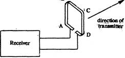
Structure ofVDF
Non-directional radio beacon (NDB)
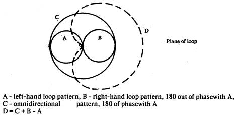
These beacons are also known as compass locators. NDBs are connected to a single vertical antenna and produce the pattern. Operating in 200 - 160 kHz bands, they have power output ranging from as low as 20 Watts up to several kiloWatts. Modem designs are 100 percent solid state.
NDB transmit vertically polarized signal in all directions from the point of transmission. An aircraft, carrying radio compass, tunes in thestaition on its frequency and measures the direction of the incoming wave with reference to the nose of the aircraft.
Emissions of radio signals are classified according to the characteristics of the signal. Different types of emissions are identified by means of a simple code consisting of one letter of the alphabet and one numeral. A stands for amplitude modulation, F for frequency modulation, Р for pulse modulation.
The numbers that are used in conjunction with NDBs are as follows:
0- the carrier carries modulation intended to convey information,
1- information is conveyed but causing breaks in the carrier wave and thus producing Morse characters,
2- information conveyed by ON/OFF keying of the modulating signal and not carrier wave.
3- information is conveyed by speech or music (telephony information) -
3.4.2. Marker beacons
Marker beacons operate at 75 MHz and radiate a narrow pattern upward from the ground. The first beacons to be used, the so called Z-markers, generated a conical pattern; later ones generated a fan shaped pattern, the axis of the fan being at right angles to the airway. The transmitter is crystal controlled and delivers up to 100 Watts. It is tone modulated, its identity in Morse code indicated by gaps in the tone.
3.4.3. VHF omnidirectional radio rangeVOR
The VOR itself has for some 30 years been the ICAO international short-range navigational aid. It consists of a ground beacon which transmits a signal from which an airborne receiver can determine the aircraft bearing from the beacon. It thus provides a simple means of flying radial path either from or towards the ground station. More recently the use of airborne navigation computers combined with VOR and DME enables the aircraft to fly desired path, other then the direct radials, thus providing an area navigation capability.
The VOR operates in the 108 to 119 MHz band. The ground station radiates a cardioid pattern that rotates at 30 rps, generating a 30 Hz sine wave at the 5 output of the airborne receiver. The ground station also radiates an omnidirectional signal, which is modulated with a fixed 30 Hz reference tone. The phase between the two 30 Hz tones varies directly with the bearings of the aircraft. Since there is no sky wave contamination at very high frequencies and no interference from station beyond the horizont, performance is relatively consistent and is limited only by major factors:
1) site error, due to reflecting objects near the transmitting facility
2) errors in reading 30 Hz phase differences in the airborne equipment
Doppler VOR (DVOR) so called since the well-known doppler principle is used in generating the ground beacon signals has considerably improved the VOR system performance since such beacons have much greater immunity from multi-path propagation effects.
3.4.4. Distance measure equipment DME
DME operates in the 960 to 1215 MHz band. The aircraft interrogator transmits pulses on one of 126 frequencies spaced 1 MHz apart. The ground beacon receives these pulses and, after a fixed delay retransmits them to the aircraft. The airborne interrogator compares the elapsed time between transmission and reception, subtracts out the fixed delay, and displays the result on a meter calibrated in nautical miles. Each beacon is designed to handle 100 aircraft.
As previously explained, the carnage and use of DME which together with VOR, permits an aircraft to be navigated, if desirable, using its on-board computers, on a course parallel to the physical position of the associated ground aid. It follows that if all aircraft using an ATC system were capable of lateral tracking and if the navigational aid in use possessed a high degree of accuracy, it would be possible to separate aircraft on lateral tracks at the same height or level instead of in a line-astern configuration, which is primarily the case at present. This capability within a system is called area navigation.
3.4.5. Instruent landing system ILS
The ILS is designed to provide an approach path for exact alignment and descent of an aircraft on final approach to a runway.
The ground equipment consists of two highly directional transmitting systems along with three (or fewer) marker beacons. The directional transmitters are known as the localizer and glide path transmitters.
The system may be divided functionally into three parts: Guidance information - localizer, glidepath Range information - marker beacons, Visual information - approach lights, touchdown and centreline lights, runway lights
1) The localizer transmitter, operating on one of the twenty ILS channels within the frequency range of 108,1 MHz to 111,9 MHz, emits signals which provide the pilot with course guidance to the runway centreline. Identification is in International Morse Code and consists of a three letter identifier preceded to the letter !(..) transmitted on the localizer frequency. Example: I - DIA
2) The UHF glidepath transmitter, operating on one of the twenty ILS channels within the frequency range 329.3 MHz to 335,0 MHz radiates its signals principally in the direction of the final approach.
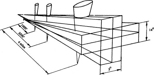
ILS beams
The glide slope transmitter is located between 750 feet and 1250 feet from the approach end of the runway (down the runway) and offset 400-500 feet from the runway centreline. It transmits a glide path beam 1,4 degrees wide. The term «glide path» means the portion of the glide slope intersecting the localizer.
The glide path projection angle is normally adjusted to 3 degrees above horizontal so that it intersects the middle marker at about 200 feet and the outer marker at about 1400 feet above the runway elevation.
The glide path facilities provide a signal which flares from 18-27 feet above the runway. Therefore, the glide path should not be expected to provide guidance completely to a touchdown point of the runway.
3) Ordinarily, there are two marker beacons associated with an instrument landing system; the outer marker and middle marker. However, some locations may employ a third marker beacon to indicate the point at which the decision height should occur when used with a Category II ILS.
The outer marker (OM) normally indicates a position at which an aircraft at the appropriate altitude on the localizer course will intercept the ILS glide path. The OM is modulated at 400 Hz and identified with continuous dashes at the rate of two dashes per second.
The middle marker (MM) indicates a position at which an aircraft is approximately 3500 feet from the landing threshold. This will also be the position at which an aircraft on the glide path will be .at an altitude of approximately 200 feet above the elevation of the touchdown zone. The MM is modulated at 1300 Hz and identified with alternate dots and dashes keyed at the rate of 95 dot/dash combination per minute.
The inner marker (IM), where installed, will indicate a point at which an aircraft is at a designated decision height (DH) on the glide path between the middle marker and landing threshold. The IM is modulated at 3000 Hz and identified with continuous dots keyed at the rate of six dots per second
3.4.6. Loran-A
Loran-A is an abbreviation of long range navigation. A loran chain normally comprises a «master» and two «slaves», it is usually installed along a coastline to serve vehicles on or over the ocean. Loran creates a hyperbolic line of position, with the master and slaves as foc. The interseption of two such lines, one from each slave provides a fix.
3.4.7. Omega
The fix is established by the intersection of two hyperbolic lines of position. These are determined by measuring the phase difference of two received signals (slaves) in relation to a third signal (master).
3.4.8. Consol
Low frequency omni range (still in limited use in the North Atlantic. Multilobe pattern rotates once a minute. It can be received by any low frequency receiver.
3.4.9. Tactical Air Navigation (TACAN)
For reasons peculiar to military or naval operations the civil VOR-DME system was considered unsuitable for military or naval use. A tactical navigational system, TACAN, was therefore developed by the military and naval forces to more readily lend itself to military and naval requirements.
As a result, the FAA has been in the progress of integrating TACAN facilities with civil VOR-DME prorgamme. These integrated facilities are called VORTAC's.
TACAN ground equipment consists of either a fixed or mobile transmitting unit. The airborne unit in conjunction with the ground unit reduces the transmitted signal to a visual presentation of both azimuth and distance information. TACAN is a pulse system and operates in the VHF band of frequencies. Its use requires TACAN airborne eguipment and does not operate through conventional VOR eguipment.
3.4.10. VHF omnidirectional range/Tactical air navigation VORTAC
VORTAC is a facility consisting of two components, VOR and TACAN, which provides three individual services: VOR - azimuth, TACAN - azimuth and TACAN distance at one site. Although consisting of more than One component incorporating more than one operating frequency and using more than one antenna system, a VORTAC is considered to be a unified navigational aid.
Transmitted signals of VOR and TACAN are each identified by three-letter code transmission, and are interblocked so that pilots using VOR azimuth with TACAN distance can be assured that both signals are being received definitely from the same ground station.
3.5. Aerodromes
The elements which comprise the overall complex are:
- access/egress facilities;
- airport landside which consists of passenger and cargo-handling buildings, including aircraft loading and unloading facilities, taxiways, runways with their related facilities such as lights and landing aids;
- airport airside. This element relates to the capacity and capability of the airport to accommodate different categories of aircraft: CTOL (conventional take-off and landing), RTOL (reduced take-off and landing), STOL (short take-off and landing), ZTOL (zoom take-off and landing) and VTOL (vertical take-off and landing);
- terminal airspace. Involved in this element is the airport's accessibility airspace restrictions to and from the airport, traffic pattern conflict with other neighbouring airports, and airspace structuring to facilitate arriving and departing aircraft.
The area of an aerodrome used for take-off consists of the runway, the stopway, and the clearway. Take-off distance requirments are determined by the stipulation that at speed VI critical engine failure speed should exist at which, in the case of engine failure, the aircraft can stop in the emergency stop distance available or continue the take-off and reach a height of 35 feet in the take-off which is able to support the aircraft during an aborted take-off without causing structural damage

Stopway
The clearway is also a strip of the same width as the runway and an extention of the runway (and stopway if there is one) which is free of any obstacles with the exception of threshold lights. It should be noted, that a clearway is not on the ground, but it is a plane extending into the air from the end of runway (not the stopway).
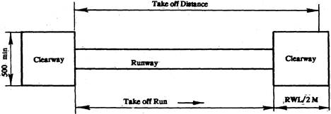
Clearway
Within certain limits, stopway, clearway and runway lengths are interchangeable on take-off. If a lower VI is selected, the emergency stop distance required (runway and stopway) in reduced, but the take-off distance required (runway + stopway + clearway) is increased.
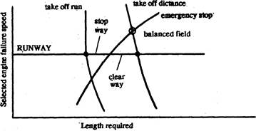
Effect on field requirements of changing VI
Figure shows that the take-off distance is minimum when the required clearway is zero, i.e. when VI is chosen so that the emergency stop distance and take-off distance are equal. This is the balanced field length. The unbalanced field length is the condition where the take-off distance and accelerate-stop distance are not equal. The emergency stop distance, called accelerate-stop distance is the distance from start of roll to stop with engine failure at VI.
The required take-off distance is the distance from start of roll to reaching a height of 35 feet with engine failure at VI, or 1,15 - times the distance from start of roll to reaching a height of 35 feet with all engines operating, which ever is greater.
The required take-off run is the distance from the start roll to the lift-off speed, with engine failure at VI.
The landing distance (which must. not be greater than runway length) is 1,67-times the distance from 50 feet to a complete stop. The landing distance is normally less then the take-off distance except in the case of some very short-range aircraft, which are required to land and take-off at approximately the same weight. However, there are requirements that no obstruction obtrude into the take-off and approach surface which are imaginary sloping planes meeting the ground respectively at the end of the available take-off distance and the runway threshold.
Several criteria have been involved for relating the strength of runways to maximum permissible aircraft weight. The subject is a complex one involving tyre pressure, the number of wheels and their distance apart, in relationships which themselves depend on the flexibility of the pavement. The criteria in most common use are the Pavement Classification Number.
Surface must be strong and graded for drainage, and scored with grooves to prevent aquaplaning, skidding on a film of water. In rain, ice and snow, friction metres (skidometers) towed at speed, measure the runway's braking action and the information is relayed to the pilot.
Noise is a major problem which affects the operation of an aerodrome. Sound is recorded in effective perceived noise decibels (EPNdB) which also measure types of noise.
A computer-drown noise footprint, is a contour map of the take-off, approach and landing noise around an aerodrome. Noise abatement procedures are applicable at very major aerodrome, and this can seriously interfere with effecient air traffic flow.
A large international airport needs most of the facilities of town sewage farms, transport services, medical centres, shops, banks, hotels, etc., apart from special airport equipment.
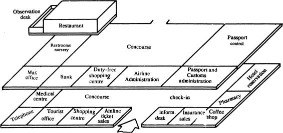
Anatomy of air terminal
Medical centres may offer vaccination as well as casualty facilities; large airports may have operaring rooms.
Staffed restrooms and nurseries are provided for passenger use at some large airports.
Duty free shops are usually positioned near the departure gates. Their use is restricted to international passengers with boarding passes.
Banks and foreign exchange counters are found in most air terminals. An airport information desk, airline ticket sales, a tourist bureau and a hotel reservation desk usually surround the concourse.
A flight information board shows flight departure, times and gate numbers, and flight cancellations. Observation desk with coffee shops, telecopes and loudspeaker quides to aircraft movements, are open to public, usually for a minimum charge.
Concourses usually located on the arrival and departure floors, are scaled to accomodate peak passenger flows with surge areas allowed for a sudden influx of arrivals, or a sudden hold-up of departures. Insurance may be bought from machines.
Airline check-in counters on the departure floor process passengers and their baggage. Passport control and Customs are necessary only for passengers on international flights; mail and telegraph facilities exist at most large airports.
Airlines have own offices, distinct from the airport administration.
The operations centre houses central computer controlling flight information display units.
At the check-in desk passengers' tickets are verified and their baggage is totalled. An average allowance is made for the passenger's weights: manual compilation of load sheets is being replaced by computer readouts to ensure that the aircraft's total weight and centre of gravity stay within limits. Here passengers can check that their luggage has been labelled with the correct code for the destination airport.
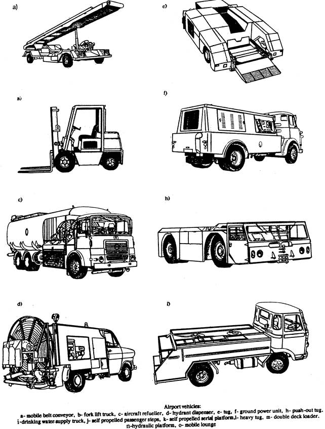
Domestic flights need no Customs procedures but there may be a security check. A special range of vehicles can be seen at any airport. Some, such as the trucks with «Follow me» signs to guide aircraft to their bays, are standard commercial vehicles.
Departures lounges (also known as holding rooms) are big enough to hold peak-season crowds.
The gates lead embarking passengers to piers, jetties, mobile lounges or air stairs.
At immigration and health control checks are made for blacklisted people, illegal immigrants, and necessary vaccination certificates.
Airoport buses, and taxis wait at ground level, and there may be park or rail termicab below ground.
Customs check for disembarking passengers may be random or work in the widely used colour coded system where travellers with declareable goods pass into one sector and others pass streight through, subject to random checks.
Long, narrow jetties reduce the surge of 300 to 500 passengers disembarking from wide-bodied jet.
Mobile belts conveyors that lift baggage up to aircraft holds, can be raised at both ends.
Fork lift trucks, highly manoeuvrable with rapid «lift and lower» speeds may carry up to 89600 Ibs (1 kilogram 2,2046 Ibs) of air cargo.
An aircraft refueller has an elevating boom on top for overwing refuelling. The largest can pump 832 gals a minute (1 gallonsa 4,546 liters).
A hydrant dispenser is linked to a hydrant supplied by the airport fuel farm. It can fuel a 747 in ten minutes. A tug carries the aircraft nose-wheel on its platform. Its high 40-mph speed is needed on the long taxiways. Ground power units (GPU) are used to start engines and to give power to electrical systems on the ground when the engines are not running. Though useful on busy aprons they are not needed at airports that supply power from ring main connected to the power centre, or by aircraft with auxiliary power unit (APU).
Commissary trucks bring aircraft cleaning and catering staff to aircraft awaiting turnaround. The body of the truck can be raised on hydraulically operated scissor legs up to the level of the passenger deck.
Push-out tugs are used to manoeuvre aircraft backwards into oddly-positioned parking bays by attaching to the nosewheel and pushing it.
Drinking-watersupply trucks holding 650 gals or more can refill an aircraft tank at 20 gals a minute.
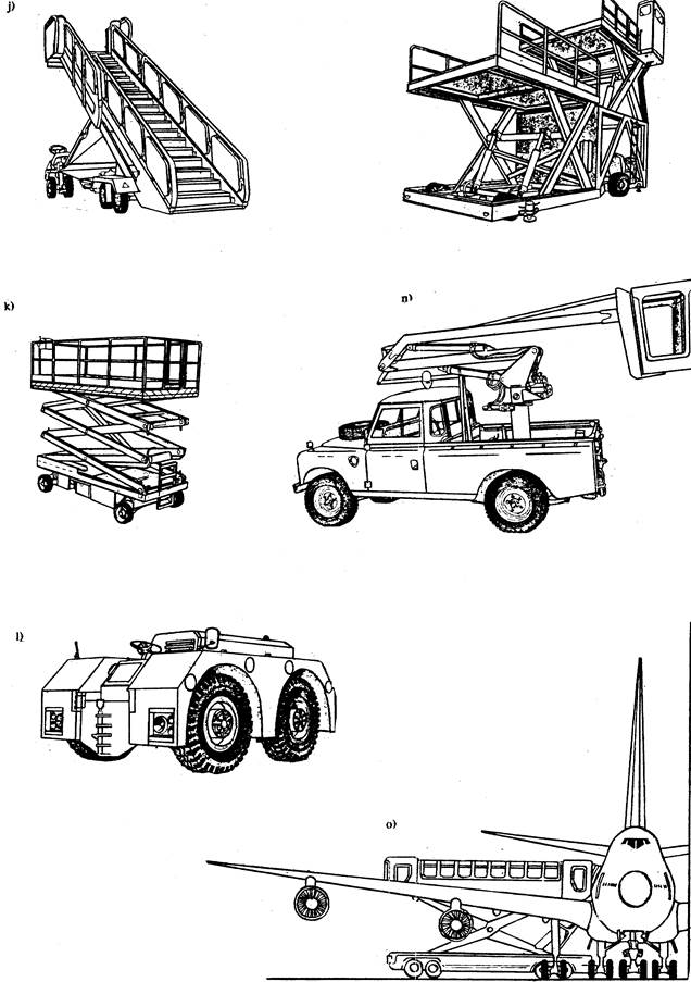
Self-propelled aerial platforms give easy access for aircraft maintenance. Heavy tugs, weighting an eighth of the 747 they pull can have a single cab or one at each end. A double deck loader, used to load air cargo pallets, has two scissor-lift platforms. The lower rises to nine feet and the upper deck mounted on a nine-feet chassis, can extend up to 18-feet deck height of a Boeing 747, this arrangement facilitates faster air cargo handling.
A hydrolic platform is used to service and clean inaccessible parts of an aircraft, such as the windscreen. Mobile lounges reduce apron congestion by conveying passengers to aircraft parked away from the terminal. Major airports are equipped with rapid intervention vehicles (RVIs) able to reach runways within two minutes of alarm. Heavy duty vehicles are designed to cross ground to reach a distant runway (by circuitious route, they cannot drive across runway in use) or the overshoot and undershoot areas where most fatalities occur. RVIs are fast trucks that carry foam; water, medical and rescue equipment and lights for use in fog and darkness. Heavy duty foam tenders are large and carry turret mounted foam guns which are able to project the foam up to 300 feet. Foam smothers the flames and cools the area around to prevent further outbreak of fire. Water is only really effective as a coolant. Powder is most effective on localized fires in wheels or tyres or in electrical apparatus.
Snow clearance operations are carried out by chains of vehicles: a high-speed runway sweeper, snow ploughs, follow snow blowers.
Marking and lighting aids
A system of markers is generally provided at all international aerodromes. The system of day markers includes runway centreline markings and touchdown zone markings.
The centreline markings are displayed not only on the runways but also on all paved taxiways. At intersections of taxiways with runways we may see holding positions markings.
The runway threshold markings consist of a series of longitudinal stripes of uniform dimensions disposed symmetrically about the centreline of the runway. The fixed distance marking may be provided together with touchdown zone markings.
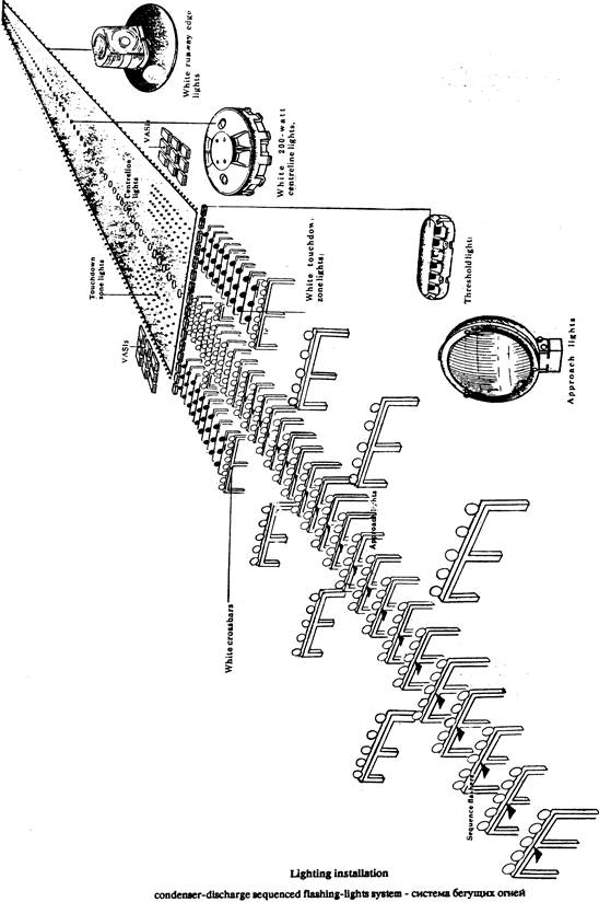
An essential part of any major airport to facilitate air traffic use day and night and under all-weather conditions is its lighting system. International standards for such lights have been established by ICAO which call for certain minimum equipment.
Some of standard installations normally installed are:
- rotating beacons to mark the location of an airport,
- approach lighting system to provide the basic means for transition from instrument flight to visual flight and landing,
- condenser-discharge sequenced flashing-light system система бегущих огней which is series of brilliant blue-white bursts of light flashing in sequence along the approach lights,
- visual-approach slope indicator (VASI) which provides visually the same information that a glide-slope unit of an ILS provides electronically in form of red and white lights to indicate the correct glidepath.
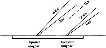

- touchdown zone and runway centreline lighting to facilitate landing under adverse visibility conditions,
- runway-end identification lights (REIL) to facilitate rapid and positive identification of the approach end of a runway,
- blue edge lights on the taxiways and sometimes green centreline lights marking the route of taxing,
Elements of aerodynamics
If an airfoil is inclined at an angle to the direction of airflow there is an increased velocity of flow over and reduced velocity of flow under the wing so that the pressure distribution is as illustrated.
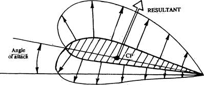
Pressure distribution
Next to the surface of the aerofoil there is a thin layer of air which retarded by friction with the surface. This is called the boundary layer.
The resultant force on the aerofoil must be at right-angles to the average direction of the airflow. This force may be resolved into two components, one at right-angles to the free airflow which is lift, and one in the direction of free airflow which is drag. The drag is usually divided into three components: skin friction drag, snap drag and induced drag. The purpose of an aeroplane's wing is to produce lift.
The aircraft wing
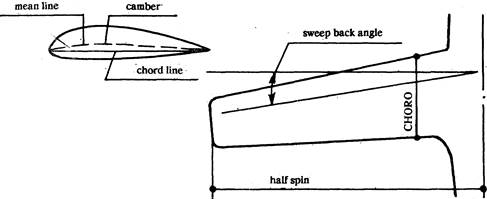
Figure illustrates the nomenclatures used in describing the size shape of a wing.
The wing span is the distance tip to tip. The chord may be considered as the straight line through the centres of curvature of the leading and trailing edges. On modern aeroplanes the length of the chord varies, the terms root chord and tip chord are used to describe chord at the wing root and the wing tip.
The mean aerodynamic chord (MAC) is the chord of an imaginary wing of constant section with the same span as the real wing and the same lift and drag.
Sweep back is the angle between the lateral axis of the aircraft and a line joining a point on the root chord one-quarter of its length back from the leading edge to a point on the tip chord one-quarter of its length back fron the leading edge.
Taper ratio is the ratio of the span to the average chord length.
The angle of attack is the angle between the chord and the direction of free airflow.
The mean camber line is a line equidistant from the upper and lower surfaces of the wing
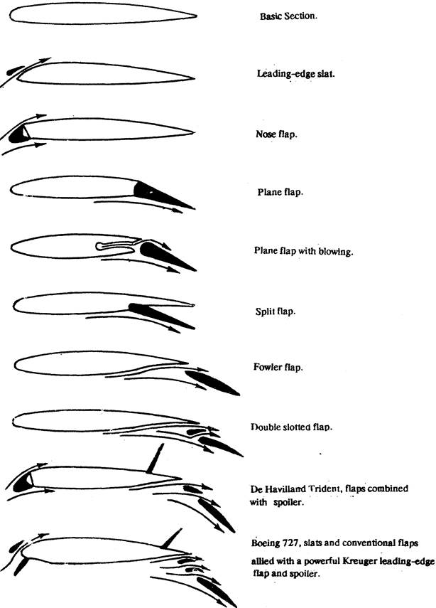
Camber changing devices
The control of section lift and drag involves control of the boundary layer. Shaping aerofoils by variations of camber, trickness distribution, slots, slats, flaps, and as well as we shall see vortex generators, are all ways of inducting the boundary layer to develop and behave in controlled manner.
Control and stability
Vocabulary
yaw damper system система демпфирования рыскания
pitch steering bar указатель углов кабрирования/пикирования
bank steering bar указатель углов крена
yaw acceleration боковое ускорение, перегрузка
scan сканирование, здесь отображение информации
There are three sets of reference axes that are significant in the measurement of stability and control the body axis, the wind axis, and the inertia axis.
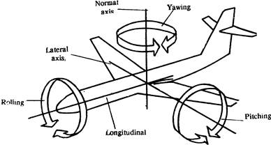
Axes of motion
The body axis have their origin at me centre of avidity (CG). Pitching, yawing and rolling takes place about the CG.
The wing axis, or stability, is the axis along which the relative wind is assumed to blow.
Although it is necessary for level unaccelerated flight that lift should be equal to weight and thrust snould be equal to drag, this is not sufficient. The third requirement is that these forces should balance, that is that the sum of their moments about any point should be zero.
Balance and control require movement of the centre of pressure. Balance is achieved by trim. When an aircraft is properly trimmed, the force on the control column in unaccelerated flight is nil.
The aircraft is statically stable if the resultant moment about CG decreases the angle of attack. In responding to the disturbance the dynamic situation inevitably appears. If the oscillations die away with time then the aircraft is dynamically stable. If a disturbance results in further divergence of the aircraft from the flight path, then it is statically and dynamically unstable.
Lateral and directional stability are two aspects of a mutual and largely inseparable problem. If the aeroplane is neutrally stable in roll, then a sideslip in the direction of jaw will follow, ending up in spiral dive. If directional stability is weak and the lateral stability is strong, then jaw will be accompanied by a roll away from the direction of yaw; a motion that reduces a sideslip and then reverses it. Resultant motion is an uncomfortable oscillation in roll accompanied by a cycle yawing. Dutch roll as the motion is commonly experienced with aircraft with swept wings.
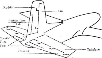
Empennage surfaces
Pitch control is effected by elevators in unaccelerated flight she aircraft is trimmed to achieve balance with zero elevator force. The coventional method is trim tabs, but some high-performance aircraft trim by altering the angle of attack of the whole tailplane which is then called in all moving horizontal tailplane or slab.
Directional control is by yaw moment produced by deflection of the rudder which is mounted on the fin. The rudder is trimmed by tab.
Lateral control is achieved by ailerons on the wings. Which are deflected in opposite directions.
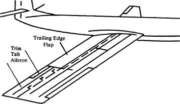
Wing's control surfaces
Ailerons may be fitted with control tabs.
For flight at comparatively low speed ailerons are placed well outboard, but as design speeds increase and aerodynamic loads with them, ailerons are placed further inbound. At high speed spoilers may be used to break down the lift of a wing,
The structure
A wide range of materials is used in the construction of an aircraft: aluminium alloys, steel, copper, wiring, rubber, magnesium, titanium, plastics, fabrics, glass, wood, lead. The mechanical properties of greatest importance are specific strength and specific stiffness.
A material is supposed to be stressed when it is loaded in a particular way. The three basic stress forms are known.
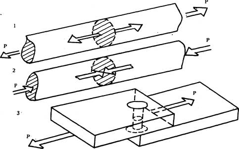
Three basic stresses
The first, tensile stress, is caused by pure tension distributed across the cross-sectional element atX-X. The
second, compressive or bearing stress, is the reverse of the tensile stress. The third, shear stress acts tangentially to the surface of contact as for example, in the given case of a rivet holding two plates together.
In flight the aerodynamic loading on the air frame is constantly changing and the inertia loading with it.
Historically the main partsr of an aircraft structure are the fuselage, wings and tailplanes.
Taking the fuselage first, the skin is usually formed of metal sheets riveted or spot-welded to metal frames, formers and bulkheads. The centre of a former is cut away, so that a former is really a stiffering outline for maintaining the form of the skin. A bulkhead is a complete section cutting like a diaphragm across a body. A bulkhead may be pierced by holes and doorways.
Running lengthwise along the fuselage, supported by the bulkheads, frames and formers and, in turn, supporting the skin are the stringers. The longerons are related to the stringers, they run fore and aft serving a major structural loading. If the skin is thick enough there may be no longerons as such, the end-loads being met by an arrangement of stringers.
Airfoil surfaces consist of spars and ribs. Ribs and skin can form the wing-tank surfaces. From the point of view of safety, interior structure (walls, ceilings, floor panels) and seat materials should be more fire-re lardant. Airline seat should have a fire blocking layer that would delay igniting of cushion material in the seats. Skins can be made of fiberglass, plastic or honeycomb filling.
Aircraft systems
An aircraft system is a set of devices which- together perform a function related to the operation of the aircraft.
3.10.7. The electrical system
The services for which electric power may be required include: engine starting, propeller pitch, engine controls flying control servos, flap motors, fuel pumps, de-icing, interior lighting, galley and toilet services, exterior-lighting, indicators and gauges, communication and navigation equipment, instruments, actuators, warning lights and sounds, nydrolic pumps.
The electrical generators are driven by the aircraft engines. Since the output is in the form of alternating current (AC) of a rrequency of the determined by the rotational speed of the generator, the frequency of the AC depends on the speed of engines. This is unacceptable for many purposes. ThereforeJt is customary for the engine to drive the generator through a constant speed unit which maintains a constant Frequency of generator output.
Certain essential services operate on a 28-volt system supplied either from the main AC through a transducerunit, the 28-voli battery, or a ground power supply.
3.10.2, The hydraulic system
With rare exceptions, hydraulics are used in airlines for operation of undercarriage, wheel brakes, nose wheel steering, flying controls, flaps air brakes and horizontal stabilizer trim. Separate selfcontained low-power electrohydrolic services may also be used for specific purpose such as windscreen wipers.
The pumps, which are the power generators in a nydrolic system, may be driven directly by the engine, but are sometimes electrically driven. A non-inflammable liquid is the usual working fluid.
Circuits and pumps are duplicated or even triplicated as a provision against mechanical failure or leakage.
3.10.3. Flight controlsystem
In relatively small aircraft the pedal and manual forces exerted by the pilot are transmitted through a system of cables and rods to the control surfaces which therefore move in direct response to the movement of the pilot's controls.
In larger aircraft the forces are impos'sibly high for the strength of a human pilot. Onesolution is an aerodynamic balance. The alternative is to use the movement of the pilot's controls only as a signal to power units which actually move the controls
The powered controls demand шоге exacting standards of reliability than any other control systems. To ensure longitudinal control in all emergencies, the elevators are electrically operated whereas the variable incidence horizontal stabilizer is powered by the hydraulic systems. Similarly, lateral control is by spoilers operated by the hydraulic system and ailerons are operated elecmcaly. In the event of total power failure, a ram-air turboalternator can be extended into the slip-stream to provide a source of electrical and hydraulic power from the air-flow on the windmilling principle. The control surfaces are in sections, each entirely independent of other and with its own power unit.
3.10.4, Fuel system
The wing is primary storage space for fuel. It has a large volume which would otherwise be useless, and the consumption of fuel does not change the position of the aircraft centre of gravity (CG) excessively.
In airliners the wing-skin itself is usually the tank which is described as an integral tank. The storage area is divided into separate tanks to avoid large motions of the fuel within the wing. An alternative system is the bag tank where the fuel is stored in collapsible bags. A leaking bag tank is difficult to identify and tedios to replace.
Each fuel tank has its own booster pumps to deliver fuel at a relatively low pressure to the engines which have their own high pressure fuel-pumps. Normally each main tank feeds one engine (with full provision for cross-feed) , and the remaining tanks transfer their contents to the main tanks as fuel is consumed. Tanks are sometimes vented to the atmosphere in such way that there is some ram effect and pressure is slightly higher than ambient.
A large aircraft may carry 100000 litres of fuel and the standard procedure is to fuel underwing at high pressure There is always provision for overwing refuelling under gravity. Pressure-fuelling facilities should not be necessary.
Fuel-quantity indicators use probes fixed at the bottom of the tank which sence, by measurement of capacitance the weight of the head of fuel above the probe. They therefore indicate the weight, not the volume, of the fuel contents.
The volume of fuel in the tanks may be checked by dripsticks-hollow tubes which are inserted underwing through a special fitting into the tanks until fuel ceases to drip through.
Although volume flow of liquid can be measured with great accuracy, the mass flow is more difficult to measure. This is one good reason why fuel is supplied by volume and not by weight. Cockpit instruments include mass flowmetres for each engine and an integrating device indicating kilos gone since engines, were started.
3.10.5. Cabin pressurization and air-conditioning
All jet airliners are pressurized. Pressurized air is supplied to the cabin either by bleed from the engine compressors or by special compressors driven by the engines and using air from ram-air scoops existing for the purpose.
Air on compression is heated. If the atmospheric lapse rate below the aircraft were dry aircraft adiabatic and if compression were exactly adiabatic the air supplied to the cabin would be at mean sea-level temperature. The air-conditioning system must therefore include facilities for both heating and cooling the air. As high-altitude air is very dry, humidification is desirable for passenger comfort.
Cargo holds are pressurized, but means of heating or cooling is either not supplied or limited.
3.10.6. Ice - prevention systems
Airliners are normally equipped for all-weather flying and protection against excessive ice accretion on leading edges of wings and tail surfaces. Propeller leading edges, engine intakes and pilot's windows are standard. Ice prevention sys the hydraulic system
With rare exceptions, hydraulics are used in airlines for operation of undercarriage, wheel brakes, nose wheel steering, flying controls, flaps air brakes and horizontal stabilizer trim. Separate selfcontained low-power electrohydrolic services may also be used for specific purpose such as windscreen wipers.
The pumps, which are the power generators in a hydrolic system, may be driven directly by the engine, but are sometimes electrically driven. A non-inflammable liquiram-air heated in a heat exchanger with turbine air: Entry guide vanes may be heated by hot air circulating inside.
The leading edges of the horizontal and vertical tail surfaces are usually heated electrically for de-icing, and so. are the propeller leading edges-sometimes cyclically.
Windscreen de-icing is usually by electrical heating through a transparent conductive sheet, laminated within the windscreen.
3.10.7. Landing gear
All modern airliners have the retractable type of undercarriage. The main indercarriageis slightly behind the most rearward position of the center of gravity possible, and the remaining weight of the aircraft is bome by the nose wheel which can be usually steered.
On large aircraft each main undercarriage bogie has four wheels and те nose-gear two wheels, making a total ten wheels. Having a large number of wheels-apart from being a protection in the event of tyre blow-out destributes the weight over a large area thus reducing runway strength requirements.
In addition to the gear itself essential provisions include: duplicate-powered system for retracting and lowering gear; emergency system for lowering gear; up-lock; down-lock; flight-deck indication of correct functioning of the systems.
3.11. Airborne computers
Digital computers
Computers generally consist of four major units: storage or memory, arithmetic and logic, control and input/output. Arithmetic unit, memory and control unit create a processor or processing unit.
Digital computers combine the basic piece of information a binary digit, bit, into groups of 8 bits (referred to as bytes) for processing. Computers operate with groups of bits; groups of bits comprising a computer word.
Programming directly in machine language is time consuming and prone to error. Programming techniques have been developed for writing the routing portion of the programme and preparing it for use by the computer.
Subroutines are extensively used not only to decrease programming effort but also to decrease memory capacity requirements. Examples include trigonometric functions, exponential, date sorting, memory load, etc..
Airborne computer design places great emphasis on high reliability. Reliability is frequently expressed in terms of mean time between failure (MTBF).
Digital computers operate on the basic of discrete numerical techniques in which variables are represented by coded pluses and/or logic states. The information content of the digital signal is expressed by the discrete states of the signal, such as the presence or absence of a voltage or a contact in the open or closed position.
Analog computers
Analog computers create physical analogies — such as voltages, shaft angles, or pulse rates — which change in accordance with the same equation as does the problem to be solved. An analog computer can solve sets of ordinary; simultaneous and nonlinear differential equations, perform coordinate transformations, multiplication, integration, and compute trigonometric functions in real time.
Analog intergrated circuits (IC) operate directly on a continuous signal to change the signals waveform amplify in, or otherwise modify it for a specific and function. Typical analog circuits are operational amplifiers — usually threeterminal devices using feedback loops and working as inverting amplifiers, summing amplifiers, impedance converters, etc. Other typical of analogy ICs are phase locked loops, voltage regulators, timers, comparators, interfaces, displays, drivers, D/A and A/D converters, sence amplifiers, etc.
Turbine engines
Engines produce thrust as an equal and opposite reaction to the change of momentum given to particles of working mass.
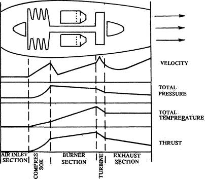
Jet air stages
Air enters the air inlet section, goes through a compressor section where its pressure is increased, enters a burner section where fuel is added for combustion, passes through a turbine section, and then leaves the engine through the exhaust section nozzle at a high velocity which produces thrust.
The turbine has a wheel which is turned by exhausted gas. A shaft connects the turbine wheel to the compressor. In general, turbojet engines are classified as either having a centrifugal and flow compressor or an axial flow compressor.
