Digital Modulation Techniques
Like analog modulation, digital modulation alters a transmittable signal according to the information in a message signal. However, in this case, the message signal is a discrete-time signal that can assume finitely many values.
Amplitude-shift keying (ASK), frequency-shift keying (FSK), and phase-shift keying (PSK) are basic digital modulation schemes.
ASK refers to a type of amplitude modulation that assigns bit values to discrete amplitude levels. The carrier signal is then modulated among the members of a set of discrete values to transmit information.
FSK is a frequency modulation scheme in which digital information is transmitted through discrete frequency changes of a carrier wave. The simplest FSK is binary FSK (BFSK). BFSK literally implies using a couple of discrete frequencies to transmit binary (0s and 1s) information. With this scheme, the "1" is called the mark frequency and the "0" is called the space frequency.
PSK uses a finite number of phases, each assigned a unique pattern of binary bits. Usually, PSK systems are designed so that the carrier can assume only two different phase angles and each change of phase carries one bit of information, that is, the bit rate equals the modulation rate. If the number of recognizable phase angles is increased to four, then 2 bits of information can be encoded into each signal element; likewise, eight phase angles can encode 3 bits in each signal element. Although any number of phases may be used, two common PSK variations are "binary phase-shift keying" (BPSK) which uses two phases, and "quadrature phase-shift keying" (QPSK) which uses four phases.
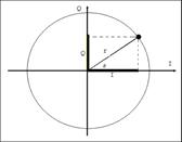
In practical systems the signal is separated into the set of independent components: I (In-phase) and Q (Quadrature). These components are orthogonal and do not interfere with each other. This may be considered as follows: the inphase component will be the real value of the signal and the out of phase component will be 900 phase shift version of the signal. A simple way to view this is by defining a signal as a vector. The signal can be expressed in polar form as a magnitude and a phase. The phase is relative to a reference signal (the carrier), the magnitude is either an absolute or relative value. On a polar diagram, the I axis lies on the zero degree phase reference, and the Q axis is rotated by 90 degrees. The speed at which the vector rotates around the circle is the frequency of the sine wave.

I-Q representations are typically used in digital communications where the amplitude, phase, frequency, or a combination of two of these characteristics, is modulated (varied) to transmit the information signal. I-Q representation provides an effective way to visualize and measure the quality of modulation.
Amplitude and phase can be modulated simultaneously and separately, but this is difficult to generate, and especially difficult to detect. This can be improved by combining ASK and PSK. This combined modulation technique is known as Quadrature Amplitude Modulation (QAM). QAM is the encoding of information into a carrier wave by variation of the amplitude of both the carrier wave and a 'quadrature' carrier that is 90° out of phase with the main carrier in accordance with two input signals. What this actually means is that the amplitude and the phase of the carrier wave are simultaneously changed according to the information you want to transmit.
Each of these techniques has a number of variations. Generally speaking, digital modulation has many advantages over the analog modulation. It provides more information capacity, compatibility with digital data services, higher data security, better quality communications, and quicker system availability. Because of this digital modulation finds more and more applications in both wired and wireless transmissions.
